Circuitry
PCB Design
The main tools that we use to design Printed Circuit Boards (PCBs) are the open source tool Fritzing and AutoCAD’s Eagle CAD.
Units in Eagle
Being Canadians, so we should be using metric units, but for some strange reason (maybe rationalized by the nature of the parts we’re using) we do a lot of stuff in imperial units. This is important when a board layout starts its journey from Eagle to Fusion. BEFORE you do the DXF file export, you must change the units from metric to imperial.
PCB Fabrication
After about a year of refining a PCB milling procedure it was decided that the cost and quality of the boards that we were producing could not match what a fabrication service could do for us so we have now switched to outsourcing our PCB fabrication. We currently use the serives of PCBWAY though we also short listed these services for future consideration:
Common Components
The following development boards are commonly used components in the prototype circuitry of our projects.
ESP32
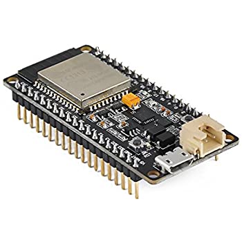 The Espressif ESP32 is the SoC at the centre of all projects at this time. The Adafriut Huzzah32 development board is the platform used for designs. The plan is to do this until the time comes to fabricate an SBC for a dedicated application.
MPU6050
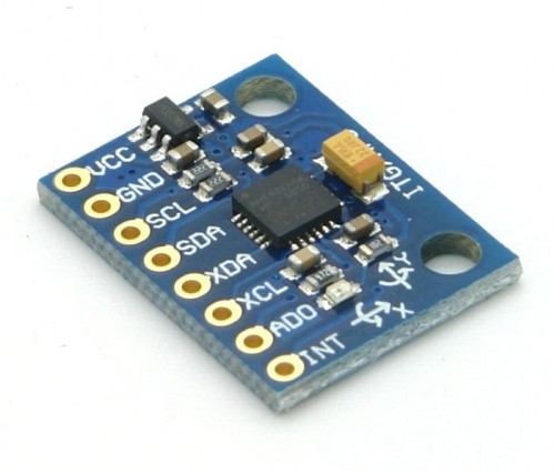 The Invensense MPU6050
MEMS
IMU
is the motion detection
SoC
of choice. The plan is to use the The GY521 development board until the time comes to fabricate an
SBC
for a dedicated application.
The Invensense MPU6050
MEMS
IMU
is the motion detection
SoC
of choice. The plan is to use the The GY521 development board until the time comes to fabricate an
SBC
for a dedicated application.
OLED
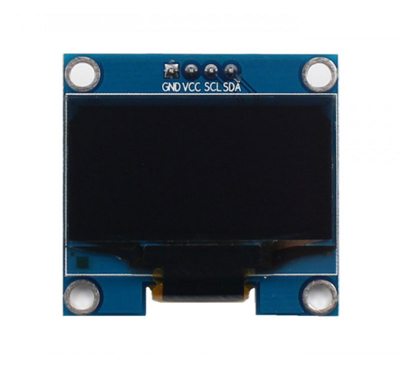 The SOLOMON SYSTECH
 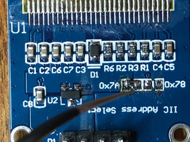 you will see a place where you can select the I2C address by moving a 407ohm surface mount resistor between two pads. You change the address by desoldering the resistor and moving it to a second pad. The addresses that you can select are shown on the silkscreen as 0x7A (01111010b) and 0x78 (01111000b). Note that when you scan the I2C bus you will not see any devices with either of these addresses. You will however see devices with the addresses 0x3D (00111101b) and 0x3C (00111100b). These are the OLEDs. Why the different address? If you look carefully at the first and second set of addresses you will notice that second 2 addresses are just the first 2 addresses bit shifted to the right one bit. This occurs becasue in common I2C communication the first seven bits of the “address byte” contains the device address and the last bit is a read/write bit. 0 is write and 1 is read. The I2C library that you are using is manipulating the addresses to conform with this convension.
DRV8825
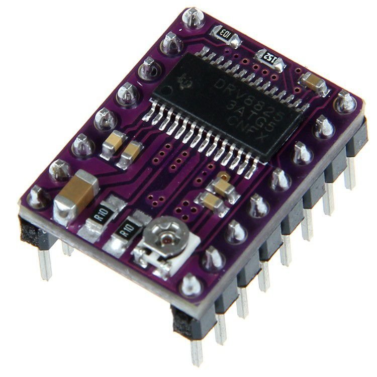 The Texas Instruments DRV8825 bipolar stepper motor driver on the Polulu Md20B breakout boards is used for controlling stepper motors.
DRV8825 Calibration Procedure
A calibration procedure is required during set up of the controller. The procedure and required circuit is detailed here. Note that the current target for the controllers is 0.4AMPS per the spec sheet linked in the Motor page. The following is a breakdown on the calibration steps:
Calculate VREF
Step one is to figure out what the target output of the DVR8825 is. This is required to ensure that the motors are not damaged by passing too much current to the coils of the stepper motors
- Our motors have a constant current rating of 0.4AMPs.
- Current Limit = VREF x 2
- 0.4AMPs = VREF x 2
- VREF = 0.4AMPs/2
- VREF = 0.2VDC
Torque Requirements
We have determined that the 0.4A motors lack the torque required to effectively balance TWIPi. We have learned that in order to increase torque we must increase the current (Amps). We have also learned that to increase speed we must increase voltage. Finally, we have learned that torque drops with speed increases.
With this new information we now realize that in order to increase the available torque we need new motors that are rated to handle more current (Amps). We are now going to try using motors rated to handle 1.7AMPS. This should give us effectively 4 times the current which we hope will produce the additional torque that we need for TWIPi.
It should also be noted that the DRV8825 motor controller that we are using can handle voltages ranging from 4 to 45VDC as well as current up to 2.5 AMPS. We have learned that by using single step mode (which we are) the motor driver only passes 71% of the current to the coils so we think we can set the current limit slightly higher which will give us another modest boost in torque. Here are the values and formulas we are using for TWIPi with the new motors:
- Vref (read with a multi meter at the POT) = 1/2 maximum current
- In single step mode we only pass 71% of the configured current limit
- We can increase the current limit on the motor controller knowing that only 71% of the current is passed to the motors
Available torque is calculated as follows: Set the DRV8825 to Vref = 0.5(1.7*(100/71)) ~= 1.2V Which in turn passes 1.7AMPS to the motor We know that the new motor is rated with a holding torque of40N.cm (56oz-in). Our old motor was rated at 37oz-in for reference. We believe this new motor will achieve its torque rating with the current we will pass it. We do not think that the old motor was achieving its advertised torque at the speed we are using. All of this is to say that we are currently hoping (praying) that by changing to new motors with a higher current rating, which in turn allows us to increase the current that we pass through the motor driver we will get sufficient torque to balance TWIPi.
Detent torque
One last not about torque. We have also learned that the maximum torque that can be achieved once the motor is moving at low speeds (which we will assume is any speed we need to balance on the spot) is calculated as follows:
Holding torque - 2 * Detent torque = 40N.cm - 2 * 2.2N.cm = 35.6N.cm
This is relevant once we get beyond simply trying to balance on the spot and actually try to move about with TWIPi.
Testing Results
With the new motor we calibrated the DRV8825 to 1.2V. This resulted in a noticeable increase in torque but we also noted that only 0.8AMPs were being drawn from the power supply being driven at 12VDC. We then tried increasing the calibration number to see if we could draw 1.7AMPS from the power supply. At over 1AMP being drawn the motor stopped spinning. As we gradually reduced the AMPs being passed the motor would run for a bit then stop. We think this was the DRV8825 using thermal protection and cutting out until it cooled down. When we reduced the calibration number back to 1.2V and the power supply indicated that it was passing 0.8AMPS then the motor ran without cutting out so we assume that the DRV8825 is no longer over heating.
Wire up tuning circuit
Use this diagram to wire up the calibration circuit DVR8825 calibration
Probe and calibrate
- Set your multi meter to read DC voltage
- Put the negative probe to ground and the positive probe to the POT
- Turn the POT until the meter reads 0.2V (200 mV)